
 Mounting an 8′ dish for a 6GHz data link on
WYDE FM’s 1326′ tower near Good Hope,
AL. Data travels over fiber and separate
power lines go to an SMPS on the ground.
![]() On This Page:
On This Page:
Different Topologies
A Simple Flyback-er
A Light Load: Discontinuous Mode
Ringy-Dingies
Using The LT8301: +/-15V
The Easy Way
![]()
Different Topologies
There are actually many different types (“circuit topologies”) of switched mode power supplies (SMPS). I’ve shown you the boost converter; the opposite is the “buck” converter. It makes an output voltage that’s lower than the input.
(That little cigarette-lighter-plug thingie that you use to charge your phone while driving? Probably a buck converter. It’s so efficient, it won’t get hot even when dropping 13.6V down to 5V at 1 amp.)
You can combine the two to create a “buck-boost” converter. I implied earlier that your smartphone has a booster. It might actually buck when the battery is fully charged, then boost when it’s weak.
I’m not going to cover all of these topologies here. We can split SMPS into two general types:
- Those which are non-isolated and typically run off batteries and
- those which are isolated and typically draw from an AC line supply.
The boost served as our example for the non-isolated type. One very common converter for isolated, AC line applications is the flyback. It uses a transformer with separate windings.
 Fig 1: Flyback operation. Don’t miss the phasing
dots on the transformer. They’re very important.
![]()
A Simple Flyback-er
I borrowed the illustration above (figure 1) from Wikipedia, edited it and added some labels, to show you one complete flyback cycle. The operation is similar to that of the boost supply. We store energy in the inductor (via the primary), then release that energy (via the secondary; the juice “flies back,” whence the name).
The voltage reverses polarity on discharge, same as with a “booster;” the phasing dots on the transformer show how we should connect things to make it work.
(For those who might not know: you create a transformer in SPICE as two or more inductors that are linked via mutual inductance. The “K1 L1 L2 1” statement in figure 2, below, is what does the magic. The turns ratio is the square root of the inductance ratio.)
In fact, with a turns ratio of unity and if we’re in continuous conduction, the output voltage is essentially determined by the duty cycle — same as with the boost supply.
 Fig 2: A simple flyback circuit
![]()
The simple flyback circuit of figure 2, above, has the same active load that I used previously for a simple boost converter. The maximum is 200mA; the minimum, 2uA. (Here’s the file if you want to play with it yourself.)
Figure 3 (below) is a zoomed view at the 180mA load point, close to the maximum design load. I’ve superimposed the primary and secondary currents to show you that we’re in continuous conduction mode (CCM): the coil(s) always have a current flowing.
(For now, ignore the switching glitches, circled in yellow.)
In CCM, with a 50% duty cycle and with a unity, 1:1 turns ratio (the primary and secondary inductances are equal) we expect the output to be about the same as the input.
Same as with the boost supply, slight drops across the MOSFET and the diode keep us from reaching the full 5V in figure 3.
 Fig 3: 180mA load, continuous mode (CCM).
![]()
Light Load: Discontinuous Mode
And now for discontinuous mode (DCM, figure 4, below): for at least part of the cycle, no current flows in either coil. This time, I zoomed in at a point where the output current was at about 4.5mA. The yellow circle shows where the coil current(s) drop(s) to the zero line.
The flyback converter adds one joyous complication: ringing. All SMPS are prone to glitches and ringing, but flybacks are especially notorious — and especially in DCM.
You can also see that the output voltage has gone up significantly, same as with a boost converter in DCM.
(If you were paying attention in Inductance 101, I showed you that the shorter the “spit” time, the higher the output voltage. Look at the slope of the secondary current.)
 Fig 4: Light load, discontinuous mode (DCM).
![]()
Ringy Dingies
Here’s a better example of ringing with a short duty cycle (figure 5, below). Look at the red portion of the switch waveform; that’s the switch “on” time.
This was taken from an earlier run of the LT8301 (below), boosting a 5V input to +/-15V. It illustrates the problem: ringy-dingies.
We RF engineers hate stuff like this, of course, because it causes interference. A good SMPS design will have filtering and “snubbers” to reduce this.
The problem is, that costs money and let’s face it, sometimes corners are cut …
 Fig 5: Ringy-Dingies in discontinuous mode.
![]()
Using The LT8301: +/-15V
Suppose you have a pro audio mixer that wants “split” supplies — positive and negative 15V at 100mA per output. You want to use it in a remote van, drawing from the 13.6V system in that vehicle.
The in and out voltages are close enough that I can use a unity turns ratio. If I need a lot of step up or step down — for example, I want to get +/- 40V from 13.6V, I’d simply increase the turns ratio, much the same as if I was building a standard AC transformer circuit.
I’m going to use Linear Technology’s LT8301 flyback controller for this. The data sheet contains a wealth of information about how it works, how to set it up, and so on; download it and read it. I’ve modified their suggested circuit for a +/-15V output for figure 6 (see below).
Note how I’ve derived -15V from the third winding (L3). I’ve grounded the “positive output” and I’m pulling from the “bottom” of that part of the circuit. However you choose to do it, never forget: the output diodes must be reverse-biased during the primary “charge” portion of the cycle.
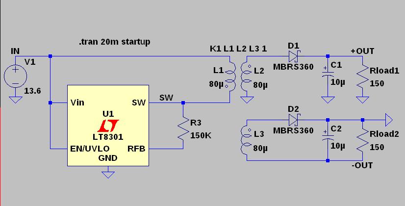 Fig 6: LT8301 making +/-15V from 13.6V.
![]()
Now for the waveforms (figure 7). The top pane shows the coil currents. The primary current is in green; the secondary for the positive output is red. The middle pane shows the positive output and the bottom pane is the negative output.
Given that the windings are all equivalent, it’s not surprising that the negative and positive outputs have essentially the same value. I haven’t shown the secondary current for the negative output, but it will be the same as for the positive output.
You can’t cheat physics: the primary must be “filled” with enough energy for both outputs during the “on” cycle. In this example, with unity turns ratios, you would indeed expect the primary current to be twice that of one of the secondaries.
This is enough to illustrate the principles. If you want more info on flyback converter design, Simon Bramble has an excellent LTSpice-oriented discussion that you can delve into.
 Fig 7: Waveforms for the circuit of figure 6.
![]()
The Easy Way
You can design and build your own supply, if you like. But for low-power applications, there’s an easier way: a small DC-to-DC converter.
I recently needed +/-5V from an unregulated “wall wart” that made 9-12V of DC. I chose the Murata NDTD1205C (PDF), a self-contained switching supply. As you can see from the picture below (figure 8), it’s in a standard-sized DIP package. (Other packages can be had, of course, including TO220 styles that look like the old 78xx and 79xx series, but are actually SMPS controllers.)
Let me repeat the mantra: always refer to the data sheet. Among other things, it will tell you the recommended load current(s). In this case, using low-powered opamps, I couldn’t meet the recommended minimum, so I added some fixed 150 ohm load resistors to each output.
A final note: you may have had a bad experience with one of these board-mounted converters in years past. The latest ones are quite reliable. Just choose a reputable vendor. TDK and Murata both make very good parts and I can recommend them highly.
Click here and I’ll finish up with some tips for choosing, using and (possibly) repairing an SMPS in the field, or use the menu to the left.
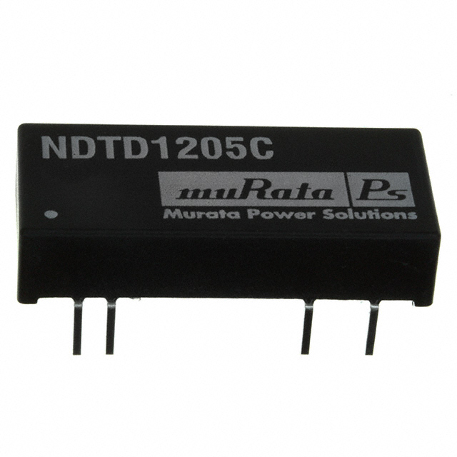 Fig 8: the easy way: a board-mounted converter!
![]()