
 “I got yer switch mode right here!“
![]()
The cat’s not in the room, so I can say it: click any of these pictures for a larger image.
On This Page:
The Real Fun Begins!
The LTC3400
At Full Load
With A Lighter Load
With A Very Light Load
Bursting
The LTC3400B
Some Final Caveats
![]()
The Real Fun Begins!
(You’ll definitely want to read this one, because this is where we uncover the Mysteries Of The Gonkulator, discussed in the introduction).
Linear Technology has a bunch of regulator ICs in their lineup, with tons of design advice. Other good sources for information include TI (look at their “Simple Switcher” series), NXP and International Rectifier.
One of the classic references is Linear Technology’s Application Note #25, Switching Regulators For Poets (PDF). It was written in 1987, but the math and design concepts are still valid.
The newest regulator ICs are easier to use: they need no compensation or special treatment. You just pop ’em into your circuit, add a few external components and you’re ready to go.
Let’s do a boost regulator using Linear’s LTC3400/LTC3400B.
 Fig 1: a boost converter that
fits on a single Roosevelt dime.
![]()
The LTC3400
The 3400 is self-contained. The switching transistor, an active diode (actually a 2nd switched MOSFET), the controller and the 1.2 MHz PWM clock are all built into a TSOT-23 case. In figure 1, above, it’s the black rectangle with 6 legs.
See figure 2. The “SHDN” (shutdown) pin turns off the regulator if the input voltage drops below .85V. “Vin” is the supply voltage, “SW” is the switching transistor and “VOut” is the output from the internal active diode.
Setting it up is easy, thanks to the “FB” (feedback) pin. All you need is a divider (R1 and R2 in figure 2) on the output. Choose values so that, when the desired output is reached, you have 1.23V on FB. The regulator will adjust the duty cycle as needed to keep it there.
The 3400 is specifically optimized to take 1.5V and boost it to 3.3V, which touches on what I’ve already mentioned. Here’s Linear Technology’s suggested application circuit for 3.3V at 50mA.
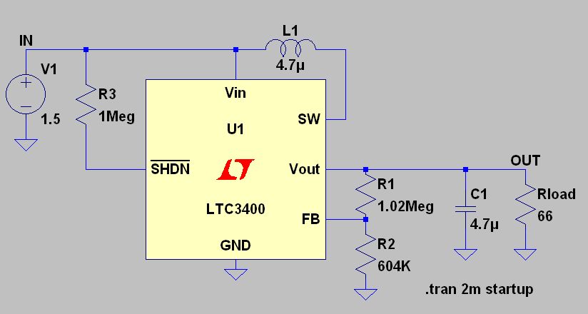 Fig 2: Suggested application circuit.
![]()
At Full Load
The 3400 runs at 1.2 MHz instead of my simple booster’s 500KHz (see the previous page). Figure 3 shows the waveforms at full load (66 ohms).
The duty cycle looks about the same, just under 60%. In fact, the waveforms look quite similar (well, except for the satanic horns on the switch waveform in the middle trace, but let’s not nitpick).
In the top trace, the current ramps up and down, as expected. The output voltage is shown in the bottom trace.
 Fig 3: 1.5V in, 3.3V out at
50mA using the LTC3400B.
![]()
With A Light Load
Let’s change the load to 660 ohms, for 5mA of output current. The top trace of figure 4 (below) shows that we’re now in discontinuous conduction mode (DCM): the coil current goes to zero for part of each switch cycle.
I haven’t covered DCM here in any detail because the math is uglier. The switching waveform in the middle trace is uglier, too (one of the satanic horns has even drooped downward). But the chip is taking care of bid’ness; that’s what matters.
Linear was going for small size. Plus, they apparently wanted discontinuous mode with light loads, so they chose 4.7uH for the coil. To get rid of DCM at lighter loads, you’d have to increase the inductance — counter intuitive, but that’s inductors for you.
Has it dawned on you yet that an SMPS likes a good load current? Speaking very generally, linear supplies are the opposite: they run hotter and the ripple increases with heavier loads.

With A Very Light Load
Suppose we make RLoad 6.6K ohms (figure 5, below). With a very light load of only 500uA, there’s a danger that the output voltage will go too high, even with a very short duty cycle.
(I haven’t specifically said this, but common sense and experience in RF would tell you that the duty cycle can’t be too short. If nothing else, the SW pin can only switch so quickly.)
Some supplies actually shut down with a too-light load — the ones in desktop computers are notorious for this. The LTC3400 is a newer chip that features what Linear Technology calls (and has registered as a trademark) (and has even patented), “Burst Mode.”
My sharper readers will remember the “whiny Gonkulator” from the introduction. Peer at the the output voltage in figure 5 (bottom trace); a light will dawn.

Bursting
With a really light load, to keep the output voltage from skyrocketing, the LTC3400 runs for a moment with the shortest duty cycle that it can make, then shuts down for a bit, then repeats, over and over.
In figure 5, the voltage stays within a safe margin, but the distance between “bursts” works out to a ripple voltage frequency of about 2KHz … right in the middle of the most sensitive part of human hearing (figure 6, below).
If you try to correct this by increasing C1, you’ll probably just lower the frequency of the “whine.” A much larger cap might eliminate it, but will cause other problems, as I’ll discuss in a moment.
At any rate, we won’t use this inside a condenser microphone, not without doing something to get rid of that whiny ripple …
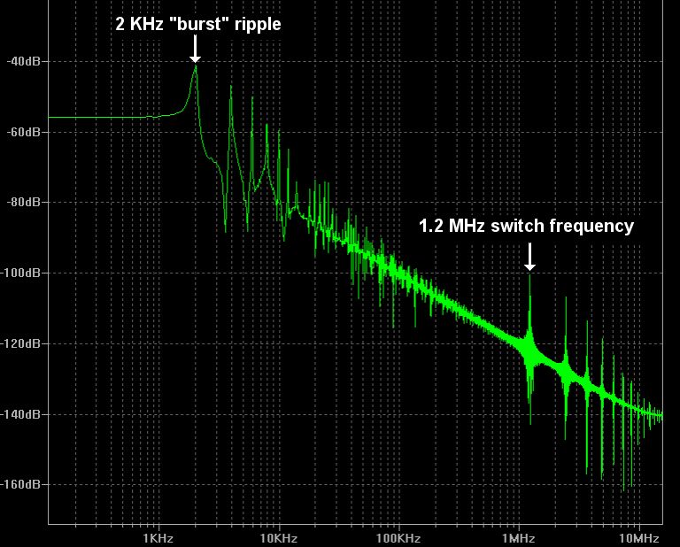
Fig 6: Spectrum of the output voltage from
the circuit of figure 2 while “bursting.”
![]()
The LTC3400B
I don’t mean to imply that “bursting” is bad; in a small portable, it can dramatically increase battery life. (That’s why Linear Technology patented it — and vigorously defends said patent).
In this example, you’ll need a much better ripple filter for audio applications, or you might add a load resistor across the output. Choose a value that will always draw enough current to prevent “bursting.” This lowers the efficiency and decreases battery life, though.
A better option is to choose (B) … as in, the LTC3400B. See figure 7 (below). This variant of the 3400 is designed not to burst.
I’ve made some minor changes (figure 7): I’ve increased L1 to 10uH and C1 to 10uF.
 Fig 7: Using the LTC3400B version.
![]()
The circuit of figure 7 uses an ultra-light 6.6K load, but the LTC3400B takes it in stride. Figure 8 (below) shows the waveforms: nice and smooth, with no bursting.
(The data sheet doesn’t say precisely how this is done, but from closely examining the simulation run, it appears that the chip is inserting a minimum load itself, and possibly pulsing the output “diode” — which is actually a switched MOSFET.)
The big point here, suitable for bold, red lettering, is: READ THE DATA SHEET. It will specify how to make that part happy, how to use it, how not to abuse it — and there will be application ideas, ready to load and run in LTSpice.
In this case, Da Sheet says that the 3400 is optimized for bursting; the 3400B is optimized to not burst. Ergo, we’ll choose the 3400B for our condenser mike. Problem solved.
 Fig 8: LTC3400B with very light loading.
![]()
Some Final Caveats
Look at the entire 10mSec sim run of our LTC3400B circuit (figure 9):
 Fig 9: The full sim run for the 3400B.
There are reasons why you can’t just throw together a big inductor and capacitor and expect your circuit to work. The values may not be critical, but this doesn’t mean that they don’t matter at all.
Simulation lets you see the mess that most circuits make when they start up. Note the current spike on the left in figure 9; if you increase C1, that’s going to worsen.
You can also see that the 3400B “stutters” a bit before it finds a stable “sweet spot.” This is not unusual. But if you increase C1 and L1, you could create a resonance at a lower frequency. Your voltage could actually oscillate up and down, especially during startup.
Figure 10 shows a bunch of yuckie — and it answers the Riddle Of The Gonkulator’s blown fuse (again, see the introduction). Just scale this up from a little battery-powered supply to the Gonkulator’s much larger AC-line-powered one.
For figure 10, I went back to the circuit shown in figure 2, with the “bursting” LTC3400. I increased C1 to 220uF; I set RLoad to 1K; and I made V1, the input voltage, switch off and on (to simulate flickering AC line power).
Yuck. You’ve heard it said that “all digital equipment should be on a UPS.” Heh. After seeing these waveforms, you’ll be tempted to say, “anything with a switched supply should be on a UPS!”
 Fig 10: The Gonkulator’s blown fuse explained.
![]()
Ponder on these things as you click to continue to a look at flyback converters.