 Real power supplies have mercury-
arc rectifiers that glow in the dark.
![]() Click any image on this page for a larger view.
Click any image on this page for a larger view.
On This Page:
Linear Juice
Analysis
The Problem(s)
In Sum …
![]()
Linear Juice
Back in the Good Old Days(tm), if you needed 12 volts DC, by golly, you wired up a transformer, some diodes and a big capacitor and called it, “good.” If you needed a steady output, a 12V regulator (such as the venerable 7812) took care of the smoothin’.
Linear supplies have the advantage of simplicity and stability. They’re easy to use. They just work … and they’re like a comfortable pair of old shoes that are ugly and that leak when it rains. We’re so used to them, we ignore their very real problems.
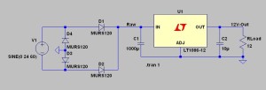
Let me show you. I’ll use Linear Technology’s LT1086-12, a 1.5A, 12V linear regulator chip, to build a familiar-looking SPICE simulation (figure 1, below).
A few SPICE-specific notes: V1 is the AC supply, set to 24V (you specify peak, not RMS) at 60Hz. D1-D4 form a classic diode bridge. C1 is the input filter and C2 is the output.
RLoad is 12 ohms, so we have 1A (i.e., 12 watts) out. Finally, “tran 1” tells LTSpice to run a 1 second transient simulation.
 Fig 1: A simple linear regulated supply;
20V “raw” DC in and 12V, 1A output.
Analysis
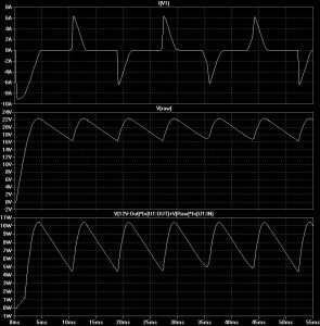
After running the simulation (here’s the schematic file if you want to try it yourself), you can click on a component or wire to bring up a current or voltage. A waveform window will appear.
That bottom pane has a terrible-looking label, but it shows the wasted energy in that regulator. If you run this simulation, press CTRL and click on that label in the waveform window. LTSpice will calculate the average for you: about 7.5 watts.
We’re losing 7.5W in the regulator, so the best case efficiency at full load is 60-65%. (It’s actually a bit worse because of other losses, such as in the diodes.)
 Fig 2: LTSpice waveforms from figure 1.
The Problem(s)…
Look again at that top current waveform in figure 2, labeled “I(V1).” V1 models a real-life transformer secondary, so this gives you an idea of how much (and when) current is being pulled from the AC supply.
Not surprisingly, the very first AC half-cycle hits over 9A, because C1 needs a full charge. Afterward, we draw brief 6A pulses to keep C1 charged. The diodes are only going to conduct when the input is higher than the voltage on C1 … in other words, on the very tips of the AC peaks.
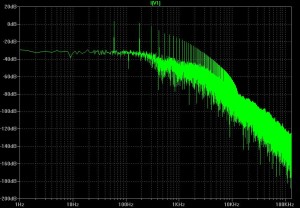
Let’s sidestep the fact that the MUR120 diode is probably not hefty enough for this application. Those sharp pulses represent a terrible power factor* and we’re generating harmonics in the power line (see figure 3, below).
Remember, you can’t “create” energy out of thin air. You’re paying to create those harmonics and they provide no useful power to your load.
Most people don’t realize that for many years, the power companies have had to correct for this and to build the capacity to handle it. By some estimates, they could provide at least 30% more power without building a single new power plant … if we’d just use the existing system more efficiently.
 Fig 3: FFT of the supply current pulses.
In Sum …
Switched mode power supplies are not only more efficient, it’s quite easy to add active power correction nowadays. One common approach is to pull sharp pulses from the power line’s AC waveform at a very high frequency. These high frequencies are easy to filter, so you can keep harmonics out of the line. Plus, you’re pulling energy from the utility over much more of each AC cycle, rather than only brief pulses at the peaks.
At any rate, power has historically been cheap in the USA, so we’ve gotten spoiled. We’ve used terrible, inefficient power supplies because we could get away with it. That has long since changed in other countries; it’s finally starting to happen here in the USA. New requirements for higher efficiency and better power factor are rapidly making the old linear power supply obsolete.
Size and cost are two more factors. 12V switch mode “wall warts” are available now that are smaller, lighter and less expensive than anything you or I could build.
The rest of this discussion will focus on switched mode power supplies (SMPS). I’ve learned to love them; let me share what I’ve found out. Read on!
 It sounds like what you might get by
sitting too long in a compact car, but
it’s an old French brand of batteries.
![]() Click here to proceed to a discussion of pulse width modulation. (Good ol’ PWM!)
Click here to proceed to a discussion of pulse width modulation. (Good ol’ PWM!)
*We people who work with ‘lecmotricity have a tendency to define “power factor” as, “ratio of reactive load to resistive.” That’s only part of it.
