
 Ah, the good ol’ days before OSHA!
“Smithers, sit in this flimsy cage and
we’ll run a billion volts through it!”
![]() Click any image here to see it full size.
Click any image here to see it full size.
On This Page:
My Introduction To PWM
Basic PWM Theory
Adding The Filter
A Class D Audio Amp
Devices For PWM/SMPS Service
![]()
My Introduction To PWM
Switched mode power supplies (SMPS) are simply a different way to use the same pulse width modulation (PWM) that we already know and love.
I remember my first encounter with PWM, back in the early 1980’s: a 5,000 watt Harris MW-5 AM transmitter. I looked at the schematic and nearly passed out when I saw the 15,000 volt(!) supply. The tubes were “stacked” in series; RF on the bottom, modulator on the top, with a filter in between to smooth the PWM into varying DC (see below).
So. First, you had a hilariously high voltage on the “top” tube (in a cabinet the size of a small walk-in freezer, mind you.) Second, the cathode in most high-power tubes is actually the filament, so the “top” tube used a filament transformer, mounted on big porcelain insulators, that had to withstand that high voltage.
(The latter was, as we engineers are oft wont to put it, “a failure point.” You haven’t lived until you’ve seen a secondary-to-primary short on one of these.)
Enough reminiscing. Obviously, I’m going to focus on how PWM is used in switched-mode power supplies (SMPS), but first, we shall have a little fun with audio.
 A simplified (crude) schematic of a
tube-type PWM modulator circuit.
![]()
Basic PWM Theory
We’ll use the LTC6992 PWM Generator chip for this. It’s a handy way to illustrate the principles with a single component.
Figure 1 shows the general idea. As the control voltage (top pane, “V(mod)”) increases, so does the width of the pulses (bottom pane, “V(pwm)”).
Here’s a caveat: Keep in mind that the “polarity” of the width modulation is actually determined by the circuit designer(s). In some cases, a higher control voltage will make a shorter pulse.
As you’ll see later, many self-contained SMPS chips make a low at the switch pin for “on,” and a lower feedback voltage makes a longer “on” time (i.e., an increased duty cycle).
 Fig 1: PWM generated by an LTC6992.
![]()
Adding A Filter
The basic principles are as follows:
- Take a stream of pulses and vary (“modulate”) the width with intelligence.
- If the pulse frequency is much higher than the modulation frequency(ies),
- you can filter the pulse and you’re left with a voltage that (hopefully!) follows the modulation/intelligence.
Here’s the LTC6992 with a filter on the output (figure 2; here’s the .ASC file if you’d like to play with it yourself).
MOD is the control voltage input and OUT, of course, is where you’ll find the output pulses. Refer to the data sheet for the LTC6992 for details.
I’ve modulated it with a 600mV peak-to-peak, 100Hz sine wave (V1 is set for 200mV to 800mV). The switching frequency is 125KHz (set by R4-R6), so I can get away with a simple RC filter on the output (R1, C1). This recovers the original “intelligence” — a sine wave.
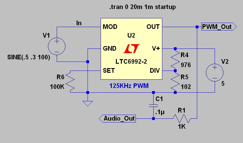 Fig 2: A slack little voltage amp.
![]()
Here are the waveforms (figure 3). I normally change all the colors to white to make these more visible as a thumbnail; I didn’t this time. Click for a larger image.
The top trace is the input voltage, the middle trace is a zoom-in on the PWM at one of the peaks, and the bottom trace is the recovered audio.
As expected, when the input hits a positive peak, the pulse is wide (i.e., has a longer duty cycle). This will leave the output switched “high” for a longer period of time, putting more juice into C1, resulting in a higher output voltage at that moment.
The input is 600mV P-P and the output is about 4V P-P. Huzzah! We have a voltage amplifier with a gain of 6.5!
 Fig 3: PWM modulated by audio.
![]()
A Class D Amplifier
It’s easy to amplify a pulse. It’s a square (well, rectangular) wave. Ergo and in other words, you can —
- modulate (i.e., vary the pulse widths) at a low level,
- use efficient switching techniques to amplify that pulse to any desired level,
- then filter the output …
… and thus, obtain even very high-level voltages and/or currents. With audio, this is commonly referred to as “class D” amplification, though other names are sometimes used.
From looking at Linear Technology’s Website, I conclude that Class D audio isn’t an area of interest for them. It took some work, but I’ve created an “amplifier” using their chips. That’s in quotes for a reason: it’s unusable as shown. I did this solely to show you some waveforms. See figure 4, below.
(If you’re really interested in class D audio amps, International Rectifier has all sorts of design information. Cirrus Logic and Texas Instruments are also good sources.)
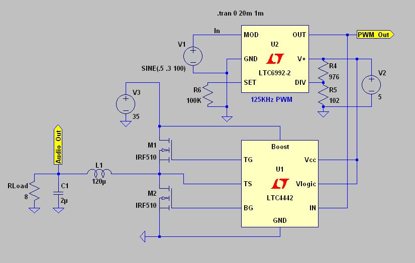 Fig 4: A Class D “amplifier” that would sound like
doo-doo and eat your speakers. (You’re welcome.)![]()
In figure 4, the top half of the circuit is unchanged. The bottom half is where the pulse is amplified, then filtered, for an 8 ohm load. I’ve added a driver chip (the LT4442) and a couple of classic IRF510 MOSFETs. V3 provides a supply of 35V for this half of the circuit, and L1 and C1 are the output filter.
Again, this is just to show you the idea; you wouldn’t want to use this as shown. There’s no negative feedback to correct for distortion, the PWM filter on the output is cheezy and (most importantly) you’d need a big output capacitor to block DC from the load (read: from your expensive speakers).
But with some refinements, you could easily get 20-30W into a 4 ohm load with something like this.
Imagine a for-real design, with big, beefy MOSFETs, a bridged arrangement, better output filter and maybe even a switching “step-up” circuit to boost the voltage for output. It’s not hard to see how a car audio maker could cram hundreds (or even thousands) of watts of class D power under the seat of a Nissan Sentra, is it?
Here are the waveforms (figure 5). Sure enough, the output follows the input, but at a much higher level.
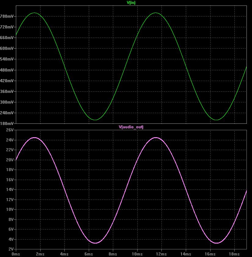 Fig 5: Waveforms from the Class D amplifier.
![]()
Devices For PWM/SMPS Service
We’ll finish with a quick look at the devices that are used in high-speed switching service. The key to high efficiency, of course, is to rapidly switch on and switch off (i.e., a perfect rectangular wave). If you can do that, very little power will be wasted in the switch, because it’s either all on, or all off.
Whether you’re building or repairing, you need to specify components that
- have low losses at high speeds/frequencies, and
- can handle brief, strong pulses of current, and/or
- brief, high voltage spikes.
That’s by no means an exhaustive list. The point is that you cannot use bargain capacitors and diodes, or stuff from your junk box. In particular:
- Capacitors: must be non-inductive and able to handle the peak current. The ESR (equivalent series resistance) must be very low. You might think that this precludes electrolytics, but there are many that are optimized for switching service nowadays.
- MOSFETS: the power dissipation isn’t as important as the peak current from drain to source. The switching times must be good, too. (The same principle applies to all switching devices, of course, but MOSFETs are the most common.)
- Diodes: also need to handle sharp peaks and the switch on/off times are critical. Standard 1N4000-series diodes will not work in a switched-mode power supply. Fast diodes (ex., schottky types) are essential.
- Inductors: must not saturate at the peak current, and (of course) should be rated and specified for the switching frequency. Not all core materials are suitable, and the color-coding on cores is NOT standardized. Check the data sheets.
- Generally speaking: thick, low-reactance copper traces on the circuit boards, everything carefully laid out, etc., etc. Haywiring and clip leads will not work in a high-speed switching circuit. (Not even if you glare at it and haughtily inform it that you’re an experienced RF engineer. It won’t care.)
Most of this is common sense and I’ll have more on this later. Click here to continue with a completely non-technical look at how inductors really work.
 I’ve circled the PWM modulator in this 500W
transmitter module. The MOSFET driver is on
the green PC board just above the circled area
and the PWM filter runs across the top.![]()